Expansion Board and Micro:bit Assembly
In this step, we will assemble the micro:bit onto the expansion board and calibrate the servo motors
The expansion board helps us connect the servoe motors and power easily from the micro:bit.
Parts Required
| Part | Quantity | Description |
|---|---|---|
| Micro:bit | 1 | Main controller board |
| Expansion board | 1 | Used to connect servo motors, IR sensor, and power |
| Small screws | 5 | Used to tighten the micro:bit onto the expansion board |
| Servo motor | 2 | Servo motor used for the leg mechanism |
Expansion Board and Micro:bit Parts
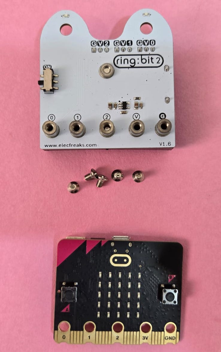
1. Place the Micro:bit on the Expansion Board
Take the micro:bit and place it on the expansion board as shown.
Make sure the gold edge connector pins of the micro:bit align properly with the expansion board terminals.
The micro:bit pins should match the labels on the expansion board:
| Micro:bit Pin | Expansion Board Terminal |
|---|---|
| 0 | P0 / 0 |
| 1 | P1 / 1 |
| 2 | P2 / 2 |
| 3V | V / 3V |
| GND | G / GND |
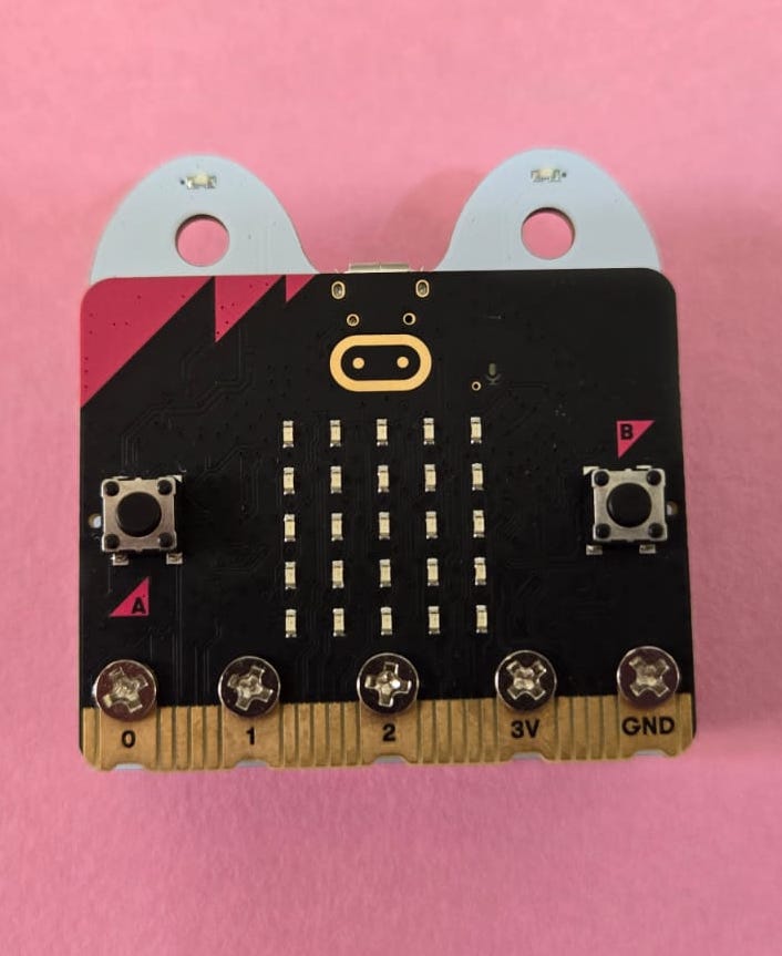
2. Tighten the Micro:bit Screws
After placing the micro:bit correctly on the expansion board, use the screws to secure it.
Tighten the screws on the following terminals:
- P0 / 0
- P1 / 1
- P2 / 2
- 3V / V
- GND / G
Do not overtighten the screws. Tighten them just enough so that the micro:bit makes proper contact with the expansion board.
Micro:bit Mounted on Expansion Board
3. Connect the Servo Motor
Connect the servo motor to P0 on the expansion board and calibrate which is essential for leg assembly
Servo wire connection:
| Servo Wire | Connect To |
|---|---|
| Brown / Black | GND |
| Red | VCC |
| Orange / Yellow | P0 Signal |
Make sure the servo connector is inserted in the correct direction.
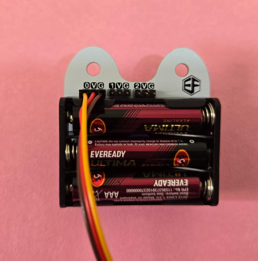
Check the following:
- Micro:bit is inserted in the correct direction.
- All five screws on the micro:bit terminals are tightened properly.
- First Servo Motor is connected to P0.
- VCC and GND connections are correct.
- Expansion board power switch is in the OFF position before connecting power.
Important Notes
- Do not reverse VCC and GND connections.
- Do not overtighten the screws on the micro:bit.
- Make sure the servo connectors are inserted in the correct direction.
If You Want to Program It Yourself Using MakeCode
Use this method if the robot program is not already pre programmed in the micro:bit.
1. Connect the Micro:bit
Connect the micro:bit to your computer using a USB cable.
Code
-
Open the above program in https://makecode.microbit.org/ by clicking on Edit Code and clicking on the arrow.
-
Click download and program the code.
Servo Motor Initial Position Setup
Before assembling the Robot Dog , both servo motors must be set to their initial position. This step is important because the servo horn position decides how the legs will move during walking.
Follow these steps:
- Insert the micro:bit into the expansion board.
- Connect the first servo motor to the expansion board.
- Turn ON the power switch on the expansion board.
- The servo motor will automatically move to the initial center position.
- Turn OFF the power switch on the expansion board.
- Do not rotate or disturb the servo shaft after it reaches initial position.
- Connect the second servo motor and repeat the same steps.
- Once both servo motors are set to initial position, continue with the assembly.
Warning
Do not disturb the servo horn or servo shaft after setting the servo to initial position. If the position changes, the Robot Dog leg movement may not work properly.